arduino-tdcs
Transcranial Direct Current Stimulation using arduino
WARNING: Using the code supplied in this project in an inappropriate way may result in SERIOUS INJURIES OR DEATH!
The code is provided in the hope that it will be useful for neuroscientists, doctors, e.t.c., but WITHOUT ANY WARRANTY; without even the implied warranty of MERCHANTABILITY or FITNESS FOR A PARTICULAR PURPOSE. Before using the code be sure that you understand that tDCS is dangerous and experts advise strongly against using it without proper training.
Transcranial Direct Current Stimulation is a neurostimulation technique used by neuroscientists to stimulate specific parts of the brain using electrodes placed on the scalp. A small amount of current, i.e., < 2mA, flows from the electrodes through the brain. Limited evidence suggests that this technique might be useful for treating various psychiatric disorders, such as depression.
The purpose of this project is to provide the software needed to perform tDCS with DIY hardware (using an arduino board, a digital potentiometer, and some extra parts). The arduino is controlled through a PC allowing to set a specific target current and monitoring the device. Then, the arduino constantly adjusts the potentiometer to keep the current within the specific limit. You can find the code, schematics, and more information in my github repo.
This is a weekend project (build in less than 24 hours) and it has not been thoroughly tested. It is provided with the hope that it will be useful for scientists interested in building and testing a cheap tDCS device. This project lacks many important components (e.g., a PID controller for controlling the current), as well as most safety mechanisms that exist in commercial products. However, the parts’ cost (not including the arduino) is less than 5$.
The software (provided here) is capable of:
- Monitoring the current flowing through the electrodes and the skin resistance
- Setting a target current and constantly adjusting the potentiometer to keep it within the target range
- Soft-starting and soft-stoping the tDCS procedure to reduce phosphenes and irritations
The following hardware was used:
- Arduino Diecimila
- 10k Digital Potentiometer (MCP4151)
- 3 status leds and current-limiting resistor
The arduino uses the SPI serial protocol to talk to the potentiometer and set the appropriate value. Then the voltage drop over the potentiometer is measured to calculate the current flow as well as the output resistance. The pinout is defined in the arduino code and it should straightforward to construct the device if you have basic electronic skills. The first electrode is connected to the ground, while the other one is driven using 5 volts from the USB port and the MCP4151.
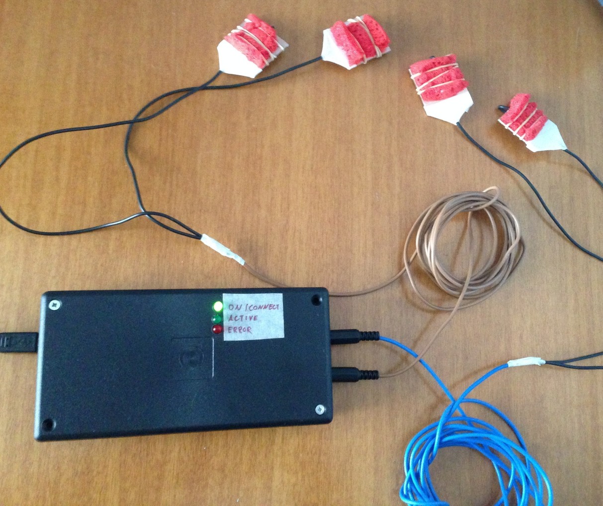
Some photos of the device are provided below, as well as some measurements to show the capability of the device to set and maintain a target current flow (within the limits of the hardware design: the wiper resistance is 75 Ohms and the minimum short-circuit current is 0.5mA).
The assembled device is shown below:
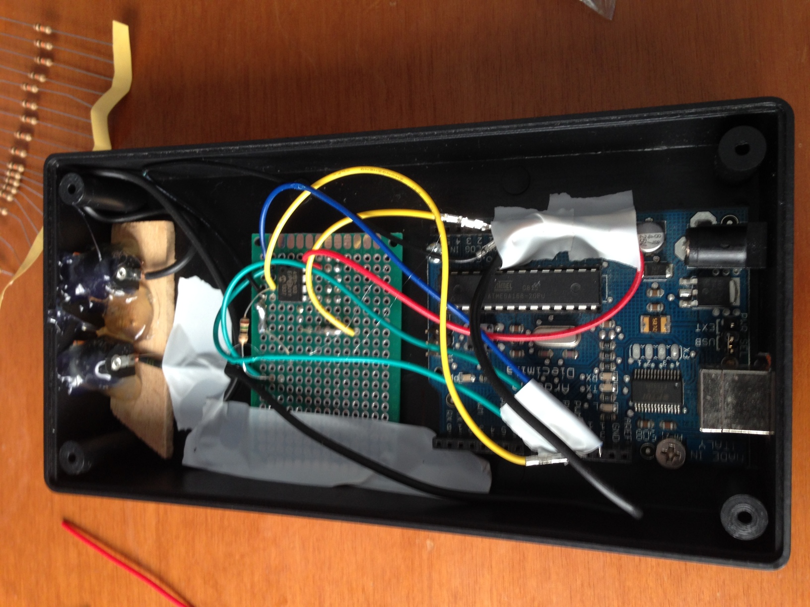
 The internals:
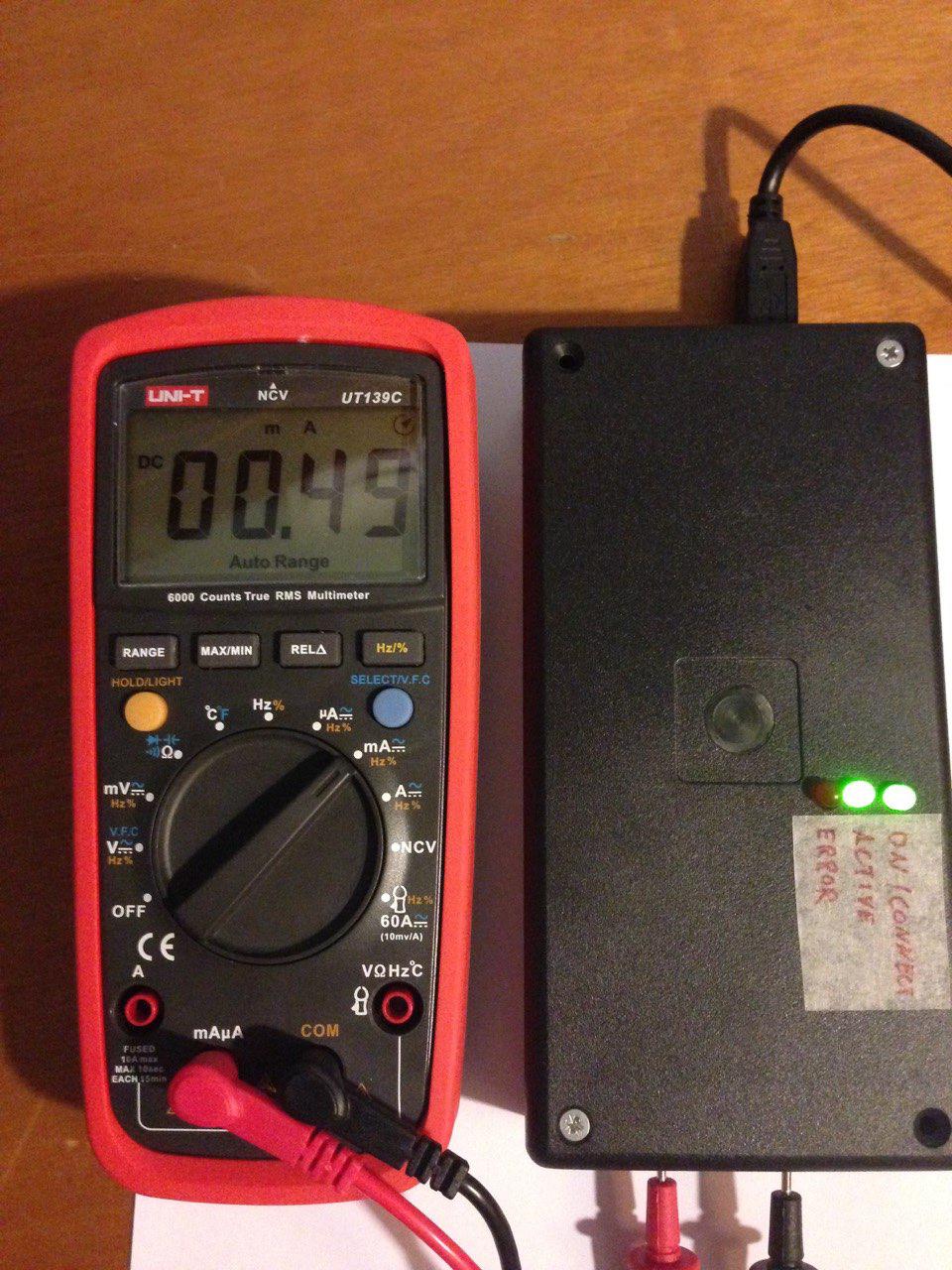
 During operation:
WARNING: Using the code supplied in this project in an inappropriate way may result in SERIOUS INJURIES OR DEATH!
The code is provided in the hope that it will be useful for neuroscientists, doctors, e.t.c., but WITHOUT ANY WARRANTY; without even the implied warranty of MERCHANTABILITY or FITNESS FOR A PARTICULAR PURPOSE. Before using the code be sure that you understand that tDCS is dangerous and experts advise strongly against using it without proper training.